Home
::
TCC1## GUIDE - Installing TORQUE CONVERTERS


TCC1## GUIDE - Installing TORQUE CONVERTERS
TCC1## GUIDE - Installing TORQUE CONVERTERS
GUIDE
Installing and Removing Torque Converters on Go Kart Engines
This guide relates to the following products:
TCC1234C_10HP
TCC121
TCC1234C
TCC1234
TCC121C
TCC123442
TCC12142
CLICK HERE to find these products on the CPR store.
This month, we're helping install your new Torque Converter - let us run you through the process to avoid any headaches and colourful language!
In this guide we'll start with a standard CPR 6.5hp engine with the clutch already removed. We will then show the procedure to install our CPR TCC1234 3/4" Shaft Torque Converter. The process is almost identical when installing the unit on a 1" (25.4mm) shaft.
If you would like to learn how to remove your existing clutch, read our guide by CLICKING HERE
DIMENSIONS
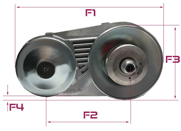
F1 = total length of backplate including pulleys: ~330mm
F2 = pulley centre to centre distance – ~170mm
front pulley diameter - ~130mm
F3 = rear pulley diameter - ~160mm
F4 = NOTE - this is not a distance, it is a view angle issue - the rear pulley does not protrude past the bottom of the backplate.
Backplate height at highest point (lowest to highest point): ~170mm
NOTE: Add approx. 5mm top and bottom for cover clearance
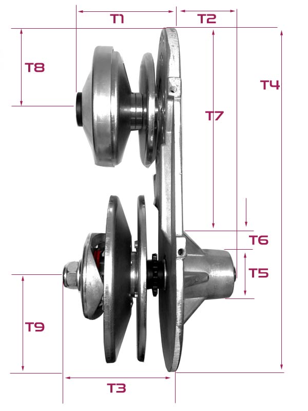
width,
T1 = (Width of backplate to front of pulley front: ~80mm
T2 = Depth of Jackshaft to rear of backplate: 60mm
T3 = Width of backplate to end of pulley retaining nut on rear pulley: ~100mm
Width of backplate to front of rear pulley: ~60mm
NOTE: Add approx. 10mm to front of pulley retaining nut on rear pulley for cover clearance)
T4 = Length of backplate: ~330mm
T5 = Diameter of Jackshaft housing: 48mm
T6 = Distance between beginning of re-inforcement bracket and beginning of jackshaft housing proper: 25mm
T7 = Unobscured length of backplate connected to engine: 195mm
T8 = Distance from front edge of backplate to centre of output shaft on engine / centre of front driver pulley: ¬70mm
T9 = Distance from rear edge of backplate to centre of jackshaft / driven rear pulley: ¬90mm
bolt hole pc:
Pre-Drilled PCDs:
4x65mm
4x89mm
CONTENTS
1. Installing the Backing Plate & Jackshaft
2. Installing the Asymetric Belt ** CRITICAL STEP - READ CAREFULLY **
3. Installing the Driver Pulley
4. Installing the cover shroud
This guide explains how to easily install a CPR TCC1234 3/4" shaft torque converterl.
1. Installing the Backing Plate & Jackshaft
Locate the four M8 short bolts in the kit. These bolts are designed to fit a standard GX200/Clone engine side plate. Nearly all clone engines use the metric fittings in the sideplates, although hole locations may differ from engine to engine. There are an assortment of holes in the backing plate. In only very very rare circumstances do the holes not line up. In this case, you may need to re-drill or slot the holes to suit.
Here is our engine with the clutch removed and the crankshaft bare, ready to install our plate. Note the four holes a the edges of the 4-point star surrounding the crankshaft. This is where our backing plate will bolt to.
- TCC1234_Install-(5).jpg (12.24 KiB) Viewed 3330 times
*NOTE - The black oil filler plug (at the HEAD side of the motor) MAY foul on the jackshaft slightly when installed. Usually a small amount of filing or cutting to reduce the amount of the plug protruding is all that is required to resolve the problem. This is quite common for most clone engines but some do not require any modification of the plug. Usually when they do foul, it's only by less than 1mm so it's easily fixed with a bastard file or similar.
Our TCC1234 system is supplied with the jackshaft and driven pulley pre-assembled for your convenience. **SOME BATCHES ARE NOT PRE-ASSEMBLED - IF YOUR JACKSHAFT AND DRIVEN PULLEY ARE NOT PRE-ASSEMBLED, PLEASE SCROLL TO THE BOTTOM OF THIS GUIDE FOR ASSEMBLY INSTRUCTIONS.** Locate the four M8 short bolts and position the backing plate as shown.
- TCC1234_Install-(7).jpg (16.05 KiB) Viewed 3330 times
Lift the backing plate up to the engine and rotate it so that four of the bolt holes in the backing plate match the four bolt holes on the engine side-plate. Ensure the bolt holes are evenly spaced from the crankshaft so that the cranshaft is centred exactly. This is very important. You can see clearly which holes are to be used in the picture when installing on a CPR 6.5hp or 10hp engine.
- TCC1234_Install-(8).jpg (15.06 KiB) Viewed 3330 times
Tighten the four bolts to no more than 12NM. Do not over-tighten as the backing plate willl be damaged.
Locate the 3/4" ring (Spacer)
- TCC1234_Install-(9).jpg (15.2 KiB) Viewed 3330 times
Push the spacer onto the engine crankshaft all the way home so that it is against the side-plate/seal/bearing. Check the position of the spacer - if you are looking down from the top or in from the side, it should line up with the outer face of the Torque Converter backing plate.
- TCC1234_Install-(10).jpg (15 KiB) Viewed 3330 times
2. Installing the Asymetric Belt *CRITICAL STEP*
The Asymetric belt is critical to the operation of the Torque Converter. It transmits power from the Driver to the Driven/Jackshaft. In addition, it rides up and down on the angled faces of the pulleys to effect the drive ratio.
The belt has two sides/faces - one face is square, and one is angled. Have a look at the two pictures below. The difference is subtle. The top picture shows the angled side, the bottom shows the square side. If you view the belt from above you should be able to see the angle on one side. The SQUARE SIDE MUST FACE THE ENGINE when installed.
- TCC1234_Install-(12).jpg (17.04 KiB) Viewed 3330 times
ANGLED SIDE
- TCC1234_Install-(12)b.jpg (11.56 KiB) Viewed 3330 times
SQUARE SIDE
- TCC1234_Install-(13)b.jpg (10.81 KiB) Viewed 3330 times
- TCC1234_Install-(14)b.jpg (19.78 KiB) Viewed 3330 times
Remove the driver from the small white box included with your torque converter and cut the zip-tie. Dismantle the unt, but leave the weight attached to the drum (G) as shown in the picture above.
Locate the flat driver pulley half (Part D in the picture above)
Slide the flat driver pulley onto the crankshaft with the flange (the part pionting upward on part D shown in the picture above) facing away from the engine. It is keyed so you will need to align the key with the keyway in the crankshaft or it will not slide on. A smaller flange (not shown - under the flat driver pulley half shown in the pic above) will but up against the 3/4" spacer you installed in part 1.
**NOTE - The 1" Version (TCC121#) does not require a brass bush - if your package contains a brass bush, it has been included by mistake*** Locate the brass ring (Part E in the picture above) and slide it over the crankshaft and onto the the flange on Part D.
- TCC1234_Install-(15).jpg (17.12 KiB) Viewed 3330 times
Orient the belt so that the square edge is facing the engine and place it over the large driven pulley (jackshaft pulley) so that it slots loosely into the groove. It will sit at the outer edge of the pulley, not deep in the groove. Then slip the other end of the belt over the brass ring (Part E). It will be fairly loose but will stay in place easily.
- TCC1234_Install-(17).jpg (14.68 KiB) Viewed 3330 times
3. Installing the Driver Pulley
Locate all the remaining pieces of the driver pulley (Part F, G & H).
- TCC1234_Install-(18).jpg (17.25 KiB) Viewed 3330 times
Slide the splined bush (Part F) onto the crankshaft so that it butts against the Flat Driver Pulley half (Part D) on the crankshaft. Note it is different on each end. The end with the two cutouts on each side of the flange is the side that must face AWAY from the engine so that the squared off parts of the hat will fit into it. It is keyed so you will need to line the key with the keyway in the crankshaft so that it can slide on.
- TCC1234_Install-(19).jpg (17.48 KiB) Viewed 3330 times
Slide the weight and drum (Part G) onto the crankshaft. You will need to align the splines but there is no speific orientation for this part except that the weight should face outwards as shown in the picture below.
- TCC1234_Install-(20).jpg (15.65 KiB) Viewed 3330 times
The Drum Hat (Part H) is then positioned on the end of the splined bush. Note that two steps ago when you installed the splined bush, that it must connect and lock the hat in position. When the hat is installed properly, it will rotate with the crankshaft. If yours is loose, it is probably because the splined shaft is installed the opposite way around.
- TCC1234_Install-(21).jpg (14.68 KiB) Viewed 3330 times
Locate the long 5/16" UNF crankshaft bolt (Part C), the machine washer (Part B), and the cap end (part A).
- TCC1234_Install-(24).jpg (15.08 KiB) Viewed 3330 times
Assemble the three parts. Place end cap on the surface with the flange facing upwards. Place the machine washer over the top of it and then thread the long crankshaft bolt up through it as shown in the picture below.
- TCC1234_Install-(25).jpg (14.9 KiB) Viewed 3330 times
Install the bolt into the end of the Driver Pulley Hat (Part H). Tighten the crankshaft bolt to approx 20Nm.
- TCC1234_Install-(26).jpg (14.87 KiB) Viewed 3330 times
Your engine should now look like this:
- TCC1234_Install-(33).jpg (15.91 KiB) Viewed 3330 times
Tighten the large nyloc nut on the Driven pulley attached to the jackshaft to align the belt perfectly.
Slip your chain over the jackshaft sprocket.
4. Installing the Cover Shroud
Locate The Shroud and the four short M6 bolts.
- TCC1234_Install-(29).jpg (15.58 KiB) Viewed 3330 times
Orient the shroud as shown with the small end over the driver pulley. Fit the shroud over the pulleys and it should line up with the 4 holes (2 top and 2 bottom) in the backing plate. Install the 4 bolts and tighten snug - do not overtighten as the thread in the billlet alloy backplate may strip.
- TCC1234_Install-(30).jpg (17.84 KiB) Viewed 3330 times
- TCC1234_Install-(31).jpg (17.12 KiB) Viewed 3330 times
WELL DONE! You have now completed the install and you are ready to drive! Have fun!

Need Help?

Gift Certificates

Categories
Bestsellers


Special
My Shopping Cart
My Shopping Cart
Cart is empty
My Account
Free Same-Day Dispatch!


Product Updates via Facebook

Get notified about our holiday times

We Accept Paypal

Outstanding Service!