GUIDE - Installing our ST1 Upgrade Kit (for GX200 & Clone)
GUIDE - Installing our ST1 Upgrade Kit (for GX200 & Clone)
GUIDE
Installing our 10hp sports hop-up kit on GX200 & Clone Engines
This month, we're turning our attention to power - and lots of it too! We'll run you through how to fit our popular 10hp sport hop-up kit to your GX200 or clone engine (or GX160).
In this guide we'll show you how to fit the unit to our standard 6.5hp CPR S engine.
If you have not already removed your governor, this guide will explain how to: http://cutpriceracing.com.au//phpbb3/viewtopic.php?f=13&t=808
CONTENTS
1. Removing existing muffler & air box
2. 2. Installing the vacuum sandwich and venturi
3. Installing the new sports muffler system
2. 4. Installing the new billet clutch & chain cover
5. Installing the fuel pump and throttle linkage systems
2. 6. Fitting vacuum lines
7. Fitting the pod air filter
8. Suggestions to replace rocker cover breather tube
2. This guide explains how to easily install our ST1 10hp Sports Hop Up kit onto a 6.5hp GX200 or clone engine.
1. Removing existing muffler & air box
(To be completed)
Remove the stock Air Filter & box, Muffler, and Fuel Tank from your engine.
2. Installing the vacuum sandwich and venturi
· Assemble & Install the sandwich plate & aftermarket billet venturi system
·
.jpg)
o Install the sandwich plate first. Gaskets are now included with the kit! Ensure that the gasket closest to the carb (bottom one) has a hole where the milled recess is on the sandwich adaptor or the system will not work correctly. Install the top gasket (D shaped centre) against the inlet manfold, then the Billet vacuum sandwich then the gasket with the small hole. The picture below has the gaskets oriented correctly for correct fitment when looking at the engine as in the picture above.
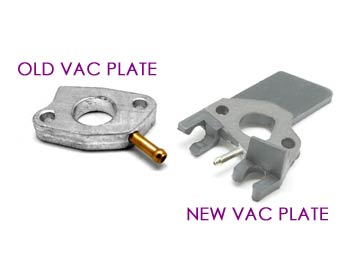
**PLEASE NOTE** The silver part below has now been updated to a BLACK bakelite version which provides superior heat insualtion and clips to retain the vacuum lines safely. It is installed the same way.
***NOTE: If you experience starting or running problems after installing the kit, double and triple check this step paying close attention to gasket order, orientation, and sandwich plate orientation ***
o .jpg)
o Feed the gaskets and sandwich plate on as shown
*** ENSURE THE RECESSED SIDE OF THE SANDWICH PLATE FACES THE CARBURETTOR and that the flat side of the plate faces toward the manifold/head***
o .jpg)
o Install the carburettor
o .jpg)
o Install the final gasket and the rubber retainer gasket as oriented below
o .jpg)
o Install the rubber gasket (orient the gaskets so that the cutout faces the top right of the carb bore and does not cover the small hole at the top right of the carb bore)
o
.jpg)
.jpg)
o
o Assemble the choke retainer bracket and venturi by installing the M5x10 Phillips head screw into the back of the venturi
o
.jpg)
.jpg)
o
o Slide the assembled billet venturi onto the studs and set the bracket so that it slides over the top of the plastic choke lever - it does not need to actually touch the lever, just retain it so that it does not slip off the shaft.
o
.jpg)
· Install the two M6 retainer nuts on the studs and tighten snug to hold the billet venturi in place
o .jpg)
3. Installing the new sports muffler system
· Install the header pipe
· .jpg)
o If your muffler was assembled by us, you will install the entire muffler assembly. If your tip and header pipe was supplied separately, just install the header for now and then screw the tip into the header at the end
o If you replaced the nuts on the exhaust studs on the engine when you removed
o .jpg)
o .jpg)
o the stock exhaust system, remove them now
o If your exhaust gasket is still in good condition as pictured then you can re-use it. If it's burnt or broken, replace it with a new one. They can be found in our store and we offer genuine honda or aftermarket - the aftermarket model is quite inexpensive (try searching for exhaust gasket)
o Slip the header on with the bend toward the polished rocker cover
(away from the crankshaft)
o .jpg)
o Tighten the nuts down snug.
o .jpg)
4. 4. Installing the new billet clutch & chain cover
· Install the sideplate
o .jpg)
o remove your clutch (if fitted) using our clutch installation guide to remove & reinstall. (Click FORUM HOME at the top of our site, then navigate the forum Technical Information & Discussion > Guides > Gearing > GUIDE - Installing & Removing Clutches or click this link: http://cutpriceracing.com.au/phpbb3/viewtopic.php?f=14&t=798
o
.jpg)
.jpg)
o
o Line up the two holes with the top holes on your sidecover and install the two XXXXXXX bolts as shown below
o .jpg)
o Reinstall your clutch.
5. Installing the fuel pump and throttle linkage systems
· Assemble the top plate
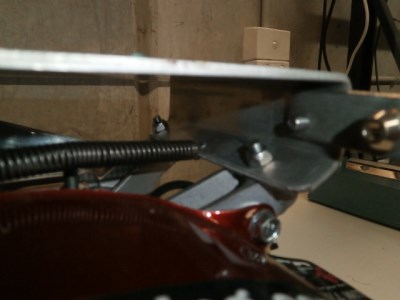
*NOTE: If you are installing your kit on a CPR S engine you will need to bend the part of the plate that kinks back, straight so that the bend is the same as the bend at the front of the plate but longer. The part that needs to be bent straight is the section you can see at the top in the picture below.
o Install the Throttle Cable seat plate on the top plate using the M6x15mm Bolt as shown below.
o .jpg)
o The plate is placed in behind the bent-over edge of the top plate with the small threaded hole away from the top plate base. Feed the M6x15 bolt through the top plate and screw it into the Throttle Cable Seat Plate and tighten.
o
.jpg)
o
o Screw the Throttle Cable Seat Cylinder into the Throttle Cable Seat Plate from the opposite direction to the bolt you just installed as shown below. Tighten the lock nut against the plate.
o
o .jpg)
o 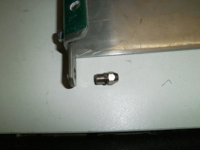

o Assemble the linkage bar by installing the Throttle Swivel Clevis. Insert into the end hole of the bar and clip the circlip over the bottom section as shown below.
o 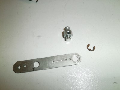
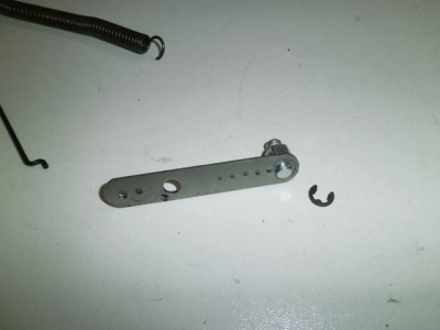
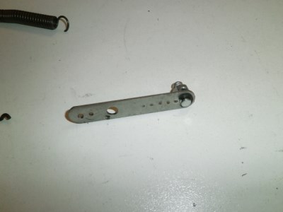
o Assemble and install the linkage rod by inserting the rod through the lightweight return spring as shown below
o
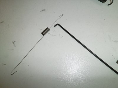

o
o Then slot the S shaped bend into the second last small hole in the end of the linkage bar on the opposite end to the clevis swivel.
o 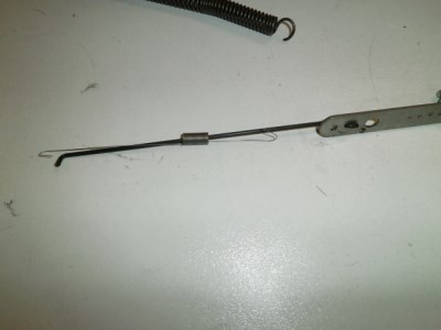
o Slip the lightweight spring end through the end hole
o 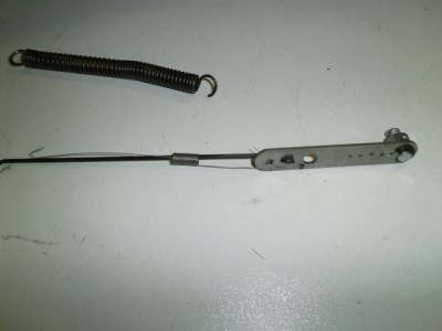
o Install the heavy return spring through the same hole
o
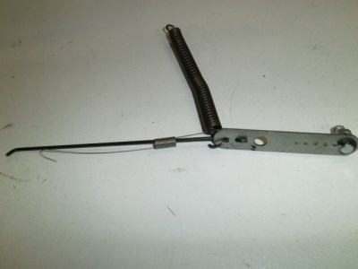
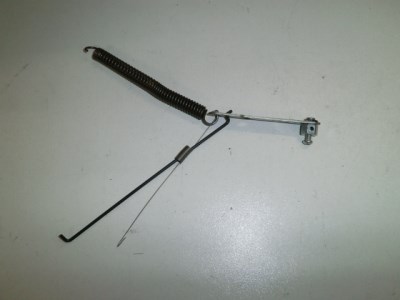
o
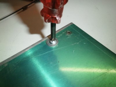
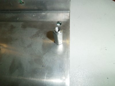
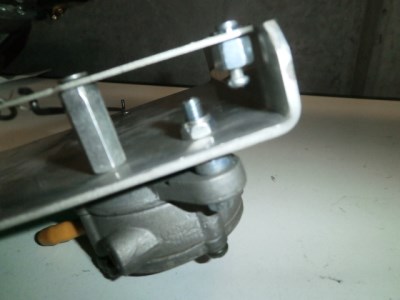
o Install the hex bar linkage spacer with the two M5 Phillips screws into the smaller hole (top hole on the left pictured below)
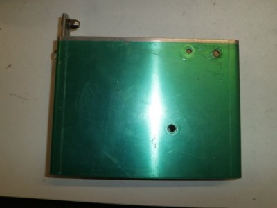
o Install the hex bar linkage spacer with the machined protrusion facing away from the bottom of the top plate - use the 6mm machine washer and one of the M5 Phillips bolts to fasten it from the top of the top plate through as shown below.
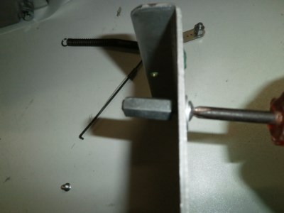
o
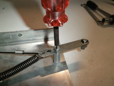
o Install the linkage bar onto the hex bar spacer as shown with one M5 phillips head bolt
o
o
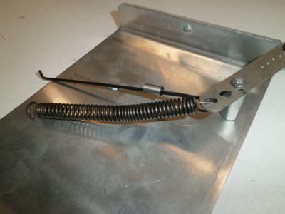
o Hook the return spring to the small hole in the end of the sideplate (the bent-over end) as shown below. Be careful as the spring may be under a small amount of tension when connected.
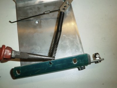
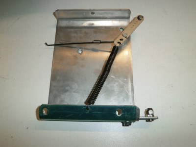
o
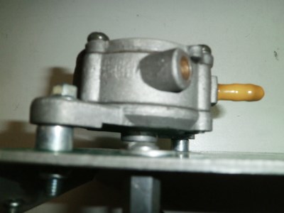
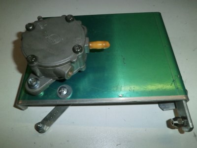
o Install the fuel pump using 2x M6x30 bolts and nylocs as well as 2x 8mm spacer cylinders. Feed the bolt through the fuel pump, then through an 8mm spacer cylinder, then through the top plate and then fix it in place with a 6mm nyloc nut. Do this for both of the tabs in the fuel pump
o
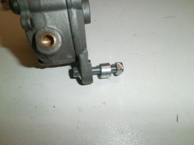
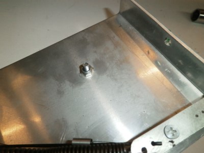
o 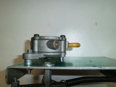
·
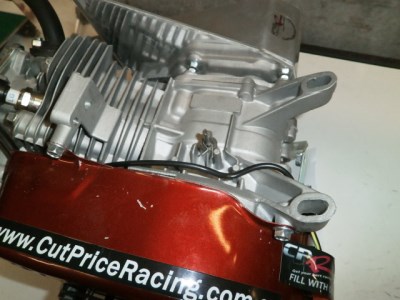
· Install the top plate by feeding the 3x M6x30mm bolts supplied through the 3x fuel tank bracket connections you removed the fuel tank from earlier in the guide.
·
· 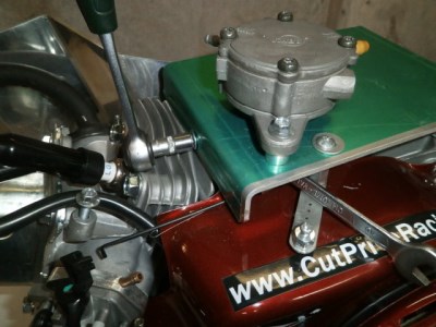
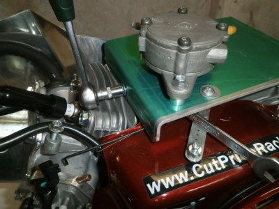
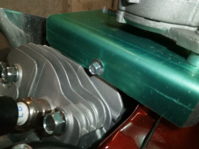
*NOTE: At this point, if you are installing your kit on a CPR S engine, the bracket holes will not match the brackets on the engine. You will need to line up the bracket and drill two new 6mm holes in the bracket. It will not sit hard up against the brackets - your long M6 bolts will reach the engine and can be bolted into the threaded brackets easily. You may opt to install some spacers or washers to fill the distance if you feel the need.
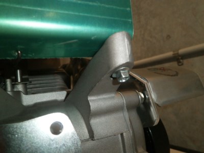
· Connect the linkage rod to the plastic butterfly bracket (slots in as shown) - push down lightly to slot it in. If you find it's difficult to insert due to having to pull excessively on the linkage, the spring you installed in the top plate may be too strong- try a lighter spring or call us for advice.
·
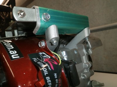
· Connect the lightweight spring to the plastic butterfly bracket (small hole)
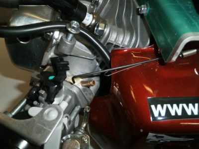

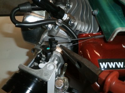
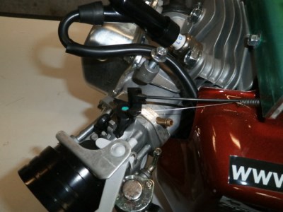
· Install Throttle cable
o Remove the throttle cable inner from the sheath (outer) by sliding the cable out.
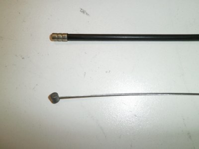
o Loosen the screw in the swivel linkage to enable the throttle cable to be threaded through
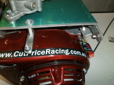
o Slide the end without the cylinder through the swivel linkage clevis then through the throttle cable seat cylinder.
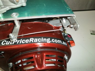
o Lock off the throttle cable by tightening the screw on the swivel linkage - do not over-tighten!
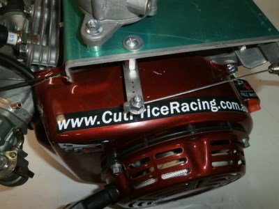
o Feed the outer sheath onto the inner and push up into the throttle cable seat adaptor cylinder.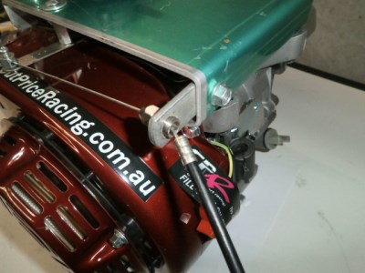
6. Fitting vacuum lines
· Install vacuum feed line.
o Place the hose clamps about 25mm onto each end of the line
o 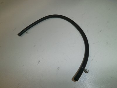
o Connect to the spigot exiting the vacuum sandwich
o 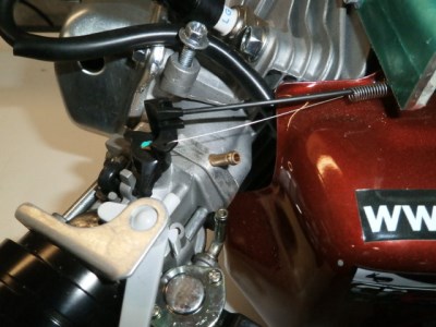
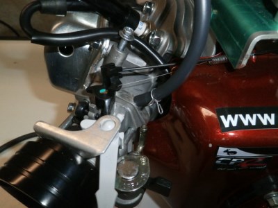
o Connect to the lower side spigot on the fuel pump and either tighten or slide the hose clamps over the end of each line
o 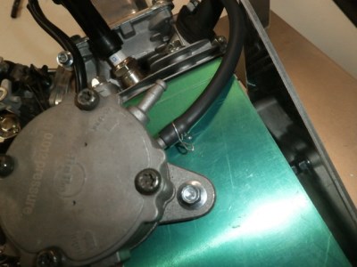
· Install fuel feed line.
o Place the hose clamps about 25mm onto each end of the line
o 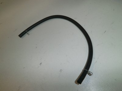
o Connect to the spigot exiting the carburettor
o 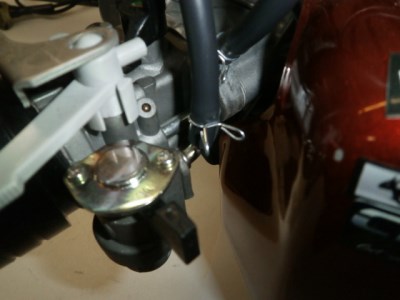
o Connect to the upper side spigot on the fuel pump and either tighten or slide the hose clamps over the end of each line.
o
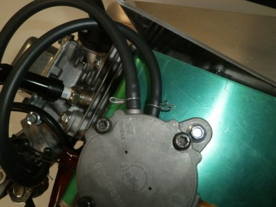
o
o Install the pod air filter over the billet venturi. Make sure you put the hose clamp on first then tighten the hose clamp with a flat head screwdriver as shown below.
o 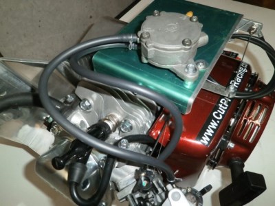
7. Fitting the pod air filter
o Install the muffler tip by screwing the end of the tip into the header pipe as shown below.
o
o
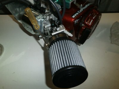
o You have completed the install!
8. Breather Tube Questions answered.
We are often asked what to do with the black breather tube that runs between the rocker cover and the original airbox (which has been replaced with the air filter after installing this kit).
The hole in the rocker cover is for venting the rocker cover. While it does not need the tube, it is possible for stray objects, dirt and other material to block the hole and render the venting void. This will cause performance issues and may cause damage to your engine.
We recommend using a standard spark-plug end-cap, drilling the centre out and pushing it into the hole. Then run some fuel tube from the back end of the cap (the part you drilled out) and run that about 150mm - hanging down from the engine. This will allow venting without anything being able to travel back up the line and block the hole.

